- One Hammer Gong Strike
- 8 day Spring Driven
- 6 inch overall dial diameter
- Wood stick pendulum
- German Movement
- 2-year warranty
- $249
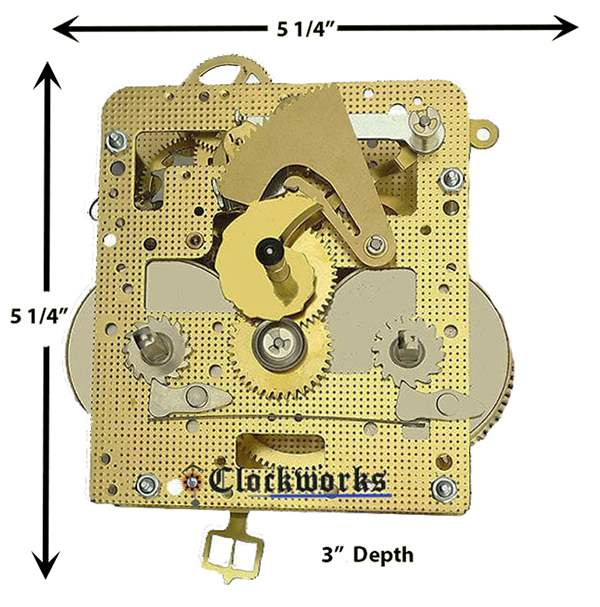
This is a quality 8 day, German made, Gong strike, spring driven movement. It has the popular 141-041 Hermle clock movement with the one hammer on the back.
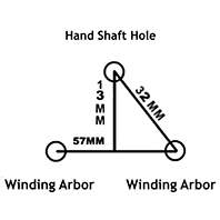
Here are some measurements you need to know to build your case, but of course the best thing to do is to get the movement first and then build the case afterward. The hand shaft, (shaft that the hands go on) is 27.2mm from the front plate and all the way out. The pendulum length on this unit is measured from the top of the clock movements suspension post and all the way down. This measurement is 55cm and includes the pendulum tip to tip, the leader it hangs on, and the suspension that the leader hangs on.
The kit comes with the movement, gong with mount, the dial, pendulum, hands and a key. This is a complete clock with out the wood case. The wood case would be typically a wall clock and this is to be built on the customers end.
Assistance = 800-381-7458

This unit is very diversified with its mounting capabilities. The mounting on this unit can either be back mount, front mount, or even bottom mount. It is possible to remove the rear mounting posts and just put hex nuts in its place, then use optional dog ear style mounts in the front. Or you can even get some seat board screws to mount the unit from the bottom.
Movement with leader and hand nut
Gong and mounting base
Round 6 Inch Dial
Dog ear style mounting brackets
Seat board washers and screws
Pendulum with its bob and nut
Serpentine Hands for a 6 inch dial
Number 8 Brass Key
Nut driver ¼ inch size
Needle nose pliers
Small hammer
Small brass finishing nails
Medium sized flat head screwdriver
Mounting Instructions
Thank you for purchasing this clock kit! This is a quality German made Hermle 8 day key wind movement that will withstand the test of time. Here are some simple instructions to get you on your way.
1. Mount the Gong
After you build your clock case you will need to mount the gong in the case first before the movement. The movements strike hammer is on the back of the movement, it is adjustable with the wire that the hammer head is on. The gong gets mounted in the back area of the movement and then the movements hammer gets final adjusted by bending the hammers wire. The hammers destination is in the center of the round gong, on the flat portion, this is where it is supposed to make contact. The hammer should be in this area and be about 1/8 inch above this gong wire when its at rest. The space between the hammer and the gong wire is so the hammer will make a crisp gong tune without double hitting, thudding, or missing the gong completely.
The gong comes with a base. This base gets secured to either the back of the clock case or to a gong mounting board that is created on the customers end. However way it is done, this is a rear hammer movement so the gong base needs to be in the area of the back of the movement. After the base is installed you can put the gong wire on its base but using the screw that is pre screwed into the base center. Take the screw off the base, put the gong wire on it, then screw it back together. Before you tighten it up too much you need to position the gong wire to its approximate position and then tighten it. I say approximate position because as previously mentioned, the hammer wire on the movement is what will be the final adjustment.
2. Mount the Movement
The Hermle 141 movement series is pretty diversified with its mounting capabilities as it can be mounted in the front, back or even bottom. It is best to come up with a mount that allows the back of the movement to be accessed without too much hassle, in case you need to change the suspension spring at some point or if the leader needs to be adjusted.
Front
For a front mounting method you would use the enclosed dog ear looking brackets and put them on the front plates pillar posts, under the hex nut that is holding the front on. Of course you would want to do only one at a time so the movement does not come apart on you, just remove one hex nut, put the bracket on, and then put the hex nut back on. Then do the rest the same way, one at a time. Since this is a front mount you’re going with, the movement will get attached to the front of the clock case with a board between the front of the movement and the clock dial. If there is rear posts on the movement that stick way out, you can remove these if you need too. They just unscrew and the movement will still be together after you do this as the pillar posts are stamped into the back plate of the movement.
Back
For a back mounting method you would use the included four long posts on the back of the movement. This will either go into the back of the clock case or a wood mount that will support the movement but at the same time not get into the way of the pendulum assembly at all. If you choose to mount in a different fashion this is fine just take these long posts right off.
Bottom Mount
If mounting this movement series from the bottom you would need to create what is known as a seat board. This is only two parallel boards that are 1x1 inch approximately that are running side to side in the clock case with about ½ inch between the two. This allows the front and back plates of the movement to each sit on a board and then be able to mount the movement with the enclosed seat board screws. The screw gets put into the rectangle washer first, and then it goes up from the bottom between the two parallel boards and into the threaded hole in the movement bottom pillars.
3. Mount the Dial
The dial on this kit is a simple white round dial with gold trim and Arabic numerals. The dial is pre-drilled for the movements winding arbor configuration so you can wind the clock with the key. The dial can be attached to a thin board via drilling holes and putting some brass finishing nails to the board. The dials positioning should be as such to have the center hand shaft hole aligned with the hand shaft itself, as well as the winding posts with there dial holes also.
4. Install the Hands
After the dial is mounted it’s time to put the hands on the clock. First comes the hour hand that is installed only in a friction fit. You put the hour hand on and twist and push down toward the dial at the same time. The more down the hour hand is toward the dial, the tighter fit it is as the hour hand post is tapered. You want it on fairly snug but not touching the dial or the minute hand that comes next. The hour hand, the dial, the minute hand should all be parallel with each other and not hitting each other during any part of their rotations.
Hands for these modern German units are designed with a rotate-able center mount in the minute hand. You need to know this as when you set up the clock at first it will not strike exactly on the hour or quarters like it should. To correct this issue it is only needed to take the minute hand off and use needle nose pliers to spin the center mounting bushing independent of the hand itself. You hold the minute hand in one hand, the needle nose pliers in the other while grabbing and spinning this center hand bushing. What this does is align that square hole in the way you need it to mount so the hand is pointing to the correct time when it chimes.
5. Install the Pendulum
The pendulum assembly consists of three components and the Germans measure all of them in one measurement. The measurement is stamped on the back plate of the movement itself in CM. The three components are the suspension spring on the very top, the leader it hangs on, and then the pendulum length all the way down to the very bottom of the pendulum rating nut threads.
When you get the movement the suspension spring will be installed but not always the leader that hangs on it. This you would put on as follows: Take the set screw out of the suspension post as to release this suspension spring and then lower it with your fingers. When the spring is lowered you are able to hook on the leader hook top, and you at the same time need that leader engaged with the crutch that swings back and forth on the back of the movement. So in other words, you will have the leader in the center of the crutch that swings it, as you hook the top to the suspension. With the leader attached to the suspension you can then bring the two part assembly up and back home into its suspension post and put in the set screw again. Now the movement is ready for casing and to be aligned with the chime block as described above. After the movement is cased and ready to go, you just hang the pendulum onto the bottom of the leader and put it in beat.
Please note !
Every pendulum clock needs to be put into beat to operate, if the clock is not put into beat it will run for 5 minutes to 12 hours and then stop every time. In many cases the complaint with a mechanical clock is that it stopped working after it was moved. This is usually from someone moving the clock without taking the pendulum off and this puts the clock out of beat. Out of beat is a term used in clock repair that basically means the clock is going tock-tick tock-tick instead of tick- tock- tick -tock. It is sometimes corrected by putting a matchbook or small piece of wood under one side of the clock case to make the tick and the tock evenly spaced. This can temporarily correct the problem and the clock runs fine. This method however is not as good as correcting the beat and having the clock run when it is truly straight and level.
You would adjust the beat by pushing the top of the pendulum left or right as it hangs in its clock case, just hold a lower portion of the pendulum with your left hand as you push the top of the pendulum left or right with your right hand. You will feel the freedom in the pendulum to move left or right, with some resistance at the sides at the end of your left or right travel. You are changing the beat of the clock when you go beyond this resistance and therefore changing the place of the freedom area. Don’t be afraid to move this pendulum top as there is nothing to break as you go left or right.
The pendulum is responsible for all the timekeeping of the movement. There is a rating nut on the bottom of the pendulum, this gets turned to get the time perfect. Timing a clock takes some time and patience to get perfect as you have to adjust it a few times to get it right. When turning this nut you are either raising or lowing the pendulums round bob at the bottom, and this positioning is what speeds or slows time. If you turn the nut to the right as to raise the bob, time will go faster, the opposite way to slow it down. The pendulum assembly consists of three components and the Germans measure all of them in one measurement. The measurement is stamped on the back plate of the movement itself in CM. The three components are the suspension spring on the very top, the leader it hangs on, and then the pendulum length all the way down to the very bottom of the pendulum rating nut threads.


