Removing the old one
Mechanical Clock Movement Removal
Removal of a mechanical clock movement is fast and easy. The movement itself is usually only mounted with two flat head screws underneath. These two screws run up into the movements pillar posts and hold it secure to the seat board. The weights and pendulum come off before doing anything to get them out of the way. This is done with a cloth so as to not stain the brass. To get to the point of removing the movement itself the dial and hands need to come off. Consequently, if the clock case is custom made by a woodworker things can get unusual. Furthermore, there are no rules with a custom case and the below trim, case, and mounting notes may not apply exactly.
Removing the hands
If the clock has a second hand, this is a press fit. All is needed to do is pull it off. There is a knurled nutknurled nut that holds the minute hand on the clock. Hold the minute hand still while loosening the nut via needle nose pliers by turning it to the left. The needle nose pliers is only to loosen the nut. Then use fingers to remove it. Meanwhile, the hour hand is only a friction fit and comes off by twisting and pulling straight up. All three of the hands are quite simple to remove.
Removing the dial trim
The trim that surrounds the clock dial would need to be removed to get the dial off. Of course, this is usually only on with two Phillip head wood screws. Remove these screws and the trim should be able to come off of the clock. It is important to have the hands off of the clock. Some trims slide down the front of the clock dial. Hence, if the hands are in the way the trim may get caught up and bend them. Clockworks does offer new clock hands if they are needed.
Choose removal with or without the dial
At this point there are two options for getting the movement out of the clock. Either with the moon dial or without it. It is usually best to remove the dial first if possible. This way it is out of the way and the movement can be worked on directly. However this is not always possible if there are no side access panels.
With the dial
The movement can now come out with the moon dial attached if this is the way chosen. The movement is only in with two screws from underneath and up into the movements pillar posts. These two screws are the only thing holding the movement in place securely. A long skinny regular screwdriver is used to take these screws out from underneath the movement. The entire unit with its dial will come out from the front of the clock. If chain driven it may require the removal of the hook and tabs from the chains. Certainly, this is needed if the seat board does not allow the chain ends to come through and out.
Getting access to the dial feet
Many clock cases are built with side access panels so they can be removed to get to the side of the movement. These panels are removed by lifting up and pushing the bottom in toward the movement. They can then be slid downward and taken out. This will allow access to the side of the movement where the dial feet can be unlocked. Upon unlocking the four dial feet (posts) the dial will then fall out the front of the clock. Best to have someone in front of the clock with gloves on to catch the dial from falling.


Unlocking the dial feet
The clock dial, or clock face, typically mounts via four posts. The four posts are part of the dial itself. Subsequently, they come off with it. These four posts lock into the front plate of the clock movement. Then they secure either with tapered pins that hold it to the movement, or slider arms that lock it in place. A tapered pin is a steel, or brass, pin that is fat on one side and skinny on the other. Just yank and twist the fat side with needle nose pliers to pull it out. Behind the front plate of the movement, the taper pin will be at the end of the mounting post of the dial. The slider arm method is even easier. Use your fingers to push it out of the way. The slider arms attach to the back of the front plate.
Phase of the moon dials
Remove the phase of the moon dial in the same manner as described above. Often there is concern because of more action on the dial. It can be intimidating at first glance. However, there is no need for concern. The phase of the moon dial is treated the same way. The only thing that runs the moon is one gear. Of course, it is called a moon gear. This moon gear is on the same tube as the hour hand. However, it is behind the dial. So in theory, it is in a location where it cannot be seen. The remaining gears that spin the moon secure to the dial. So when the dial comes out all the gears come out with it.


Movement removal
Once the dial is gone, it exposes the movement. All of the components are off of the clock and out of the way. Next, remove the two screws from underneath the movement. The movement will then lift up and out from the front of the clock case. It will come out as one big gear meatball and can be replaced. It is as simple as that. Please email if needing assistance.
How to make a Seat Board
Making a Grandfather-Clock Seat-Board
Making a Grandfather-Clock Seat-Board, which is the mount that the weight driven movement sits upon, is fairly easy.
Of course, the movement sits on this with cables or chains. Subsequently, they hang directly down between the boards.
Typical approximate dimensions
Additionally, many of the modern clocks have a seatboard that is 16 inches wide and is 2 and a half inches deep. However this varies depending on the clock case dimensions.
In the center of the mounting board is a hole that is 1 inch wide. It goes across the center of the 2 and a half inch deep seat board.
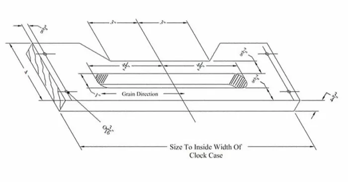
Putting it together
The hole is wide enough for the movement to sit on the board with its chains hanging down in the center. Then the seat board screws and washers can go up into the movement’s arbors on the bottom.
These are the screws with the rectangle washers. Of course, an easier method would be to mount two, three quarter or 1 inch square boards running parallel, which are 1 inch apart, across the inside of the clock case. This is really all a mounting board needs to consist of.
The only thing that has to happen is the movement is in the air with the chains dangling down in between these boards. The boards just can’t be so wide that the pendulum rubs it on the back of the movement.
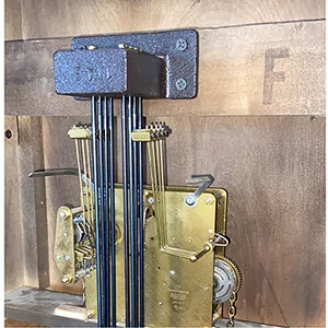
With the movement mounting in the air, all that needs to be done is have the chime block mounted.
This goes on the back of the clock case. This enables the hammers to engage with the rods for the chime sound. Next hang the weights and pendulum. The final step is to lock the dial into the movement from the front.
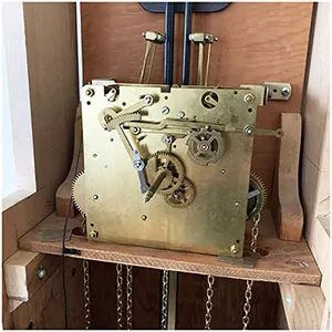
A plywood seat board
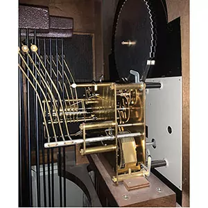
Many ways to make a seat board
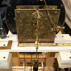
A simple test stand

Clock case seat board
Preparations to the new
Mechanical Movement Installation Preparations
Mechanical clock movement preparations start with getting the new movement out of the box and set for installation.
Cable driven preparations
The new unit may or may not have orange clips over the plastic cable drum covers if its a cable driven unit. These are uses sometimes so the cable underneath the cover will not jump over itself and get all tangled up. They are on with just a friction fit and just pull off of each cable drum. The clear plastic over the cable drum stays on the movement and this is so the cable will not jump the line and end up crossing itself. The brightly colored clips would be over the clear drum and that gets removed only. The orange clips are only to reinforce the plastic cover's job during shipping.
Chain driven movements
The chains may have fallen off the movement completely during shipping and this is how to reinstall them. Take note on the chains there is one end with a tab and the other with a hook. The hook side is what attaches to the weight and goes on the side of the ratchet that does not spin. In other words the ratchet wheel on the movement spins one way and not the other. So the chains gets looped over the ratchet wheel so the hook side of the chain goes down on the side of the ratchet that will not spin. It is fine to flip the movement upside down or whatever needed to do to get this done.
Installation preparations are now complete
The new movement is already oiled so this is not a concern. Put movement on the seat board with the cables or chains hanging down in between the seat board as it was before. Screw the screws in and make it finger tight and then a little more with a flat screw driver. This concludes this section on Mechanical Clock Movement Installation Preparations.

Trim and moon dial off

Sometimes the hood slides off

Removed with dial attached

Another hood that slides
Hanging the weights
Mechanical Clock Weight Installation
The weights may or may not all weigh the same however they usually do not. It is needed to know what weights goes on what chain or cable for most floor clocks in existence. Typically there is differences on the weights from left to right on a mechanical floor clock. This section is referring to post WW2 modern floor clocks of German origin.
Mechanical clock weight placement
A bathroom scale can let us know if either there is two heavy and one light weights, or two light weights and one heavier. The chime side will always take the heavy weights and the strike side will always take the light weights. The middle time train is left to be variable dependent on the pendulum bob diameter. The pendulum bob is the round disk at the bottom of the pendulum. If it is a wide bob or if the pendulum is heavy for other reasons, it will take more weight. If more weight is required on the center time train it will be the same weight as the chime side instead of the strike side.
Weight Installation - The heavy one
The chime weight will always be the heaviest weight there is for the clock every time. This is the weight that goes on the right while facing the clock. If there is a weight that is heavier than the rest it goes on the chime side. What is meant by chime side is the side that makes the songs go every 15 minutes. If the wrong weight is on this chime side the clock will chime very slow and may stop in mid chime.
The Variable
The next one is the time train. This is the one that goes in the center of the three weights on the clock. If it is a heavy pendulum or the bob diameter is larger at 8 1/2 inches or 10 1/2 inches wide, its best with another heavy weight equal to the chime side. There are alot of clocks in the world running with the lighter weight when it should really be heavier and the clock runs fine for 30 years. So its not that big of a deal, but to be correct this is what it calls for. If the pendulum is heavy and the light weight is on there instead of the heavy one, the clock may or may not stop randomly.
The Light one
The lightest weight if there is one, goes on the left while facing the clock. This is the strike train side and this makes the clock bong out whatever hour it is. If the wrong weight is on this side, it may bong out the hours faster than what is intended. This will not be bad for the movement in anyway, its just what is comfortable to listen too.

Clock weight

Clock chain

Weights on cables

Use cloth to hold
Pendulum Assembly
Clock pendulum components description
Altogether, this is a description of the clock pendulum parts and components. Please use this as a glossary for parts in a clock pendulum assembly.
Knowing the correct terms for the various pendulum parts is helpful when ordering replacements. We are quite adept at deciphering descriptions of parts however, knowing the name is always something we welcome.
The clock pendulum
First, a clock pendulum includes the bottom rating nut and threads, the pendulum bob, and top hook.
Additionally, these items are removable on wood stick pendulums only. Lyre metal clock pendulums do not have the ability to come apart.

Clock pendulum leader
Second, a leader is the part that the pendulum hangs onto when it is on the clock. It then in turn hooks to the suspension spring on the very top of the pendulum assembly.
Naturally, pendulum leaders vary depending on the manufacturer of the clock movement and they can also vary in length, as well as style. Sometimes there can be more than one type of leader for the same movement.
There are also instances where we custom make leaders for customers.

Suspension spring description
The clock pendulum suspension spring is the short spring steel part on the very top of the pendulum assembly. Its purpose is to suspend the leader and pendulum in the air. Generally speaking, its steel, spring like strips, flex to let the pendulum swing back and forth with ease and momentum.

Clock Pendulum Components Complete
In summary, the clock pendulum components include the pendulum hanging on the leader and the leader hanging on the suspension spring.
Put the complete pendulum assembly on the clock and it is ready to go. The next step is to put the clock in beat and run the clock to see how the time keeping is.

Setting the beat
Mechanical clock movement beat-setting
Mechanical clock movement beat-setting means the tick and the tock sound of the clock are even. In order to run, every mechanical clock that has a pendulum needs to be put in beat. It is amazing how many clocks have not run for 10 years or more just because this is not known. Often, clocks in tag sales, auctions, and homes only need to be put in beat to run but unfortunately they were left to sit for years. The setting of the beat is easy and takes less than a couple minutes to do.
Every mechanical pendulum unit needs it
Every mechanical clock that has a pendulum needs to be in beat to function. Part of owning a clock is to know how to do mechanical clock movement beat-setting. If this is not known how to do this, then whenever moving the clock from here to there it will stop after 5-10 minutes. So learning one simple solution will keep the clock running for years.
Putting a post WW2 German clock in beat
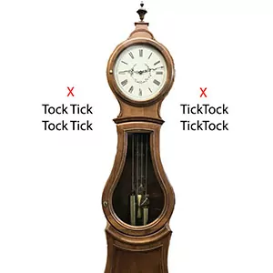
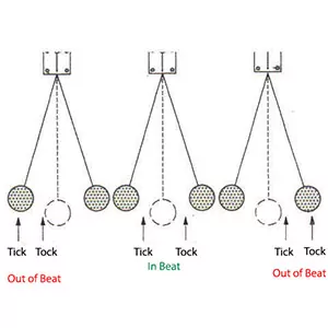
By over swinging the pendulum, most modern German mechanical clock movements can be put back into beat. This is also known as Auto Beat and is found in most post WW2 German clock movements. It's the first thing to try when a clock will not stay running. It is ok to try this even if the clock doesn't have auto beat built in. If the clock sounds like ticktock ticktock, instead of tick-tock tick-tock, or even tocktick tocktick, then it is not in beat. The clock may stop after 5 minutes, or even an hour, if it is still not in beat. Will also hear an uneven tick and tock. A rhythmic tick-tock tick-tock can be heard when it is correctly in beat.
Skinny clock case beat setting
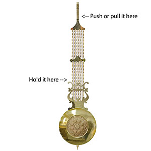
If it is not an auto beat or the clock case has a narrow width, mechanical clock movement beat-setting is done differently. Push the top of the pendulum left or right as it hangs in its clock case. Hold a lower portion of the pendulum with the left hand and push the top of the pendulum left or right with the right hand. There will be some resistance in the pendulum when moving it left or right. The beat of the clock will change when the pendulum goes beyond this resistance. Don’t be afraid to move this pendulum top left or right as there is nothing to break. However, twisting the pendulum can break the suspension spring. It is only meant to go back and forth.
Mechanical Clock Movement Beat-Setting Notes
The beat is the rhythmic pulsations of the escape wheel clicking over one tooth at a time. This results in the tick tock sound as each tooth "escapes" from the rocking anchor that blocks it. The anchor rocks back and forth from the pendulum motion and is only on its arbor by friction fit. In other words, it will rotate independently of the arbor it is riding on. The tick or tock sends a jumping pulse action to what is known as a crutch. Then this crutch whacks the pendulum slightly with each swing. The back and forth momentum of the pendulum, in addition to the whacking motion made by the crutch, keeps it going and going. However, this is provisional depending on whether it's even, left and right. Or in other words, the tick and tock are even. Once this happens, the mechanical clock movement beat-setting should be complete.
Out of Beat
Push Pendulum
Beat Setting

Now in Beat
Adjusting the hammers
Why does Chime Hammer Positioning Need to Occur
Mechanical clock chime hammer positioning is easy to do. It only involves bending the hammer head wires. Upon the initial installation, this was done by the clock maker as well.
When replacing a clock movement you need to bend the chime hammers to the chime rods. This is why the hammer heads are on bendable wires.
They are meant to be bent into the perfect position. It is not uncommon to bend them an inch this way or that way. The clock movement will not have the hammers in the perfect spot to make the correct sound when hitting the rods. This is why chime hammer positioning is so important.
Clock Chime Hammer Positioning
A mechanical clock movement has hammers that need to be bent into their final position. The correct clock-chime hammer position needs the tops of the hammer heads to be about 1/4 inch down from the chime block.
The hammers need to be 1/8 inch away from the rod. This would be when it is at rest. In other words, bend the hammer wires so the head is 1/8 away from the chime rod. This spacing between the head and the rod is so it will not thud or double strike.
Tuning the mechanical clock chime
Repeat this process for each wire, one hammer at a time, down the line. Continue in this manner until you can lift and drop the hammer to create a crisp sound. If each hammer head is done this way the clock will have a nice song in the end.
Often a customer will say the sound is not correct. This is due to improper hammer positioning. When performing the above directions correctly the sound is beautiful.
Positioning the 340 / 341 series
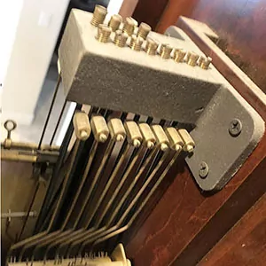
The 340 and 341 Hermle clock movement series went through a change in the hammer wires. The hammer heads were on wires, but now they are made on flat bars. The positioning is still the same, however it is a little more difficult to bend them.
The hammer head is on the skinny end of the bar. The bar gets wider as it goes back toward the roll pin.
With needle nose pliers, bend this bar where it goes from skinny to wide. The overall assembly will be slightly higher from the chime block. That is, if you are swapping out the movement with the older style wire hammer head rod.
It is an option to raise the entire chimeblock with a shim to help with this. It is not an absolute requirement. Bending the hammer arms are usually sufficient.
For a clean crisp chime sound
Adjust the hammer wires
Should be about 1/8 away at rest

Sometimes they are bent to the extreme
If it wont chime
Grandfather Clock Chime Issues
When a grandfather clock has issues with the chime functioning these are some basic corrections. The chime is the song that plays every 15 minutes and not to be confused with the strike. The strike is what calls out the hours after it is done with the chime song. This section will resolve chime issues that are not the fault of the clock movement itself. In other words what falls into the realm of being a set up issue instead of a movement issue. Please note that post WW2 German mechanical clocks are designed so that if turning the hands fast or stop the clock for a long while it may not chime for up to 3/4 of an hour. This is because the clock is looking for the top of the hour so it does not lose its place as to when to chime.
Could be looking for the top of the hour
First thing to do is see if it chimes after 3/4 of an hour. Go forward with the minute hand with fingers while going slow past the quarters. A faint click can be heard and at that point pause and see if it starts chiming. If it does not chime go forward to the next and the next quarter. If the minute hand goes all the way around for an hour with no chime, continue to the next section.
Silent switch and roll pin
There may be a switch at the 3 o'clock and this switch turns the chimes on or off. If the clock is a triple chime movement, meaning it has three songs, it will have the song selection and also silent on this switch. The movement may have this switch but the dial may not have a slot to get at it on some Westminster only units. If this is the situation access it from the back of the clock instead. Not all movements have the silence switch. So if there is no switch then this cannot be the reason for no chimes.
If it's a Westminster only unit, UP is off and DOWN is chime. However, only if there is a switch. When the clock selector switch is on chime and still does not work, the next thing to check is a jam in the roll pin. To correct this pull all the chime side hammers back all at once and then let go. This will release a jam in the chime roll pin and let it bounce into position. Shipping may cause the roll pin to jam up like this. Changing the chime song when the current song is in midstream can cause this same issue.
Weights, cables, or chains not right
Confirm the heaviest weight is on the right while facing the clock. This is the chime side of the clock and requires the heaviest weight of them all. Check the cables or chains that they are not rubbing anything on their way down to the weight. In other words, the chains or cables do not rub the seat board, pinch or wrap around the movement pillar, or anything like this. They should be straight from the ratchet wheel or cable drum and straight down to the clock weight with nothing rubbing. If the cable or chain is rubbing something it will cause resistance. Resistance is what makes a clock stop because there is not enough weight to drive through whatever is rubbing. So if the chain or cable is rubbing something it's the same as not having the right amount of weight on the clock.
ANSO = Automatic Night Shut Off is on
Higher end mechanical clock movements sometimes include an ANSO feature. This stands for Automatic night shut off, and the intention is to have the clock be silent automatically from 10pm to 7am (usually). It is possible that it thinks it's night when it's really day, and therefore will not chime. If the clock does not chime it will not strike, so therefore the clock remains silent. This being a mechanical clock, it has no sensors to determine on its own what is night or day. Solution is to go around 12 hours with the clock hands. If there is an ANSO feature on the clock movement the switch would usually be on the left when facing the clock at 9 o'clock. On some movements it is between the hand shaft and the 3 o'clock selection switch in the middle of the dial.
Setting the strike
Mechanical Clock Strike Setting
Mechanical clock strike setting is not hard. Some simple fixes can correct any problems. This information is for a new unit straight out of the box. Subsequently, for installation into an existing clock case. However it is also practical for other situations where there are strike issues German clocks. The strike issues can be from not striking at all to not striking the correct hour or striking forever. All of these strike issues reside in the same location mainly. This location is on the front side of the German mechanical clock movement.
No strike cause
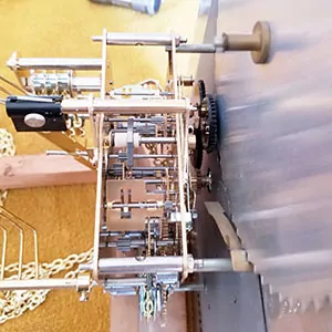
When the new movement is not striking out the hour the dial and hands come off of the clock. With the dial and hands out of the way we can see the front of the movement where the problem is. German units have a rack and snail count system. This only means there is a rack that looks like a saw on the front side of the movement. This saw looking rack falls on the portion of the hour hand tube that looks like a snail. This is why we call it a rack and snail count system. The rack is supposed to be in the up position by default and drops down onto the snail when its ready to strike.
Making the mechanical clock strike
During shipping the rack can fall behind the snail instead of on top of it. With the rack stuck behind the snail when the minute hand is installed it can squash the snail into the rack. This will cause the rack to not be able to be lifted because there is too much resistance and so the clock will not strike. The solution is to have the dial off and just lift the rack back up with the fingers. If none of this makes sense there is a simple solution and that is just to take the minute hand off for an hour and let it run for an hour with the chimes on.
The rack and snail count system explanation
The top most hump on the snail exposes only one tooth on the rack and allows the gear train to run only enough to strike one time. The deepest hump on the snail is 12 teeth on the rack and therefore 12 strikes on the top of the hour. The rest of course are all the other hours but that sort of takes care of itself. As long as one and 12 are good the rest is good.
Putting on the dial
Grandfather Clock Moon Dial Installation
A Grandfather clock moon-dial installation explanation is in this section. Thus, this is written for a new movement installation in mind.
However can use it for any post WW2 German mechanical unit with issues in relation to the front of the movement.
The moon gear
Install the moon gear onto the new movement prior to the clock moon-dial installation. It mounts with a set screw and sits on the same tube as the hour hand.
Install this onto the new unit. Of course it has to be the same as it was on the old movement. Ideally, with the same approximate distance on the hand shaft. In essence, this will allow it to run the gears behind the clock moon-dial and therefore run the phase of the moon.
The selector switch
A selector switch is a steel arm that is about 1 to 2 inches in length with a set screw. In short, the purpose of the switch is to select the song or silence the clock. Install the selector switch on the arm which is on the right side of the movement.
In other words, slide the switch over the larger arm and secure it with the set screw. It only has to be able to come through the slot at the 3 o'clock position for the user to move it up or down on the clock moon-dial.
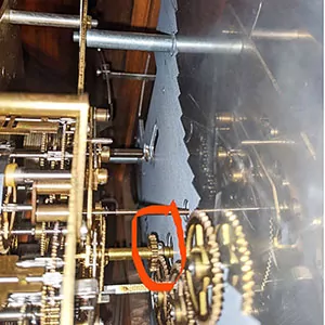
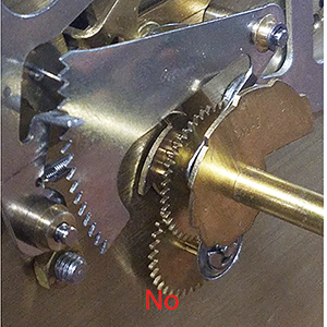
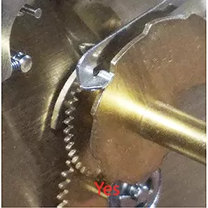
Before install, check this
These modern clock movements from Germany use a rack and snail count system for the strike. Be sure the rack tail for the strike is on top of the snail instead of stuck behind it. See pictures that illustrate the correct and incorrect positions.
Simply lift the rack back up into position with fingers. If this is not done the clock may not run, chime, or strike. It is important to get this done before completing the grandfather clock moon-dial installation.
Grandfather clock moon dial installation
The clock moon-dial has four posts on the back that lock into the front plate of the movement. Line up the clock hand shaft to the hole in the center of the dial. Then line up the posts with the holes in the movement.
There are two ways to secure the four dial posts to the clock movement. One way has locking arms on the back of the front plate of the movement that slide over the end of the dial post to lock it tight. This is if both the clock moon-dial and the movement are made this way.
The other way this is done is if there are holes in the ends of the dial post feet. These use a pin to secure it to the movement. A tapered pin will go through the hole in the post after it's on the front plate of the movement.
Moon Gear
Moon Gear Mesh
Rack Incorrect
Rack is Correct
Installing the hands
German Mechanical Clock Hands Installation
German Mechanical clock hands Installation is easy and fast. Germans used bushings in both the hour and minute hands. Where as the American units have the bushing in the hour hand only. This section describes the German style with bushings in both. The hour tube will have the round bushing installed, the minute hand will have a bushing that has a square hole in it instead. For most clocks mechanical post WW2 the hour hand has a 4.5mm round hole, and the minute hand has a 2.2mm square hole. There are exceptions to this such as the larger tubular bell grandfather clocks. Also some movements made by Jauch of Germany. The rest is pretty consistent with the hand attributes as described.
Installation of the hands
Installation is easy. Hour hand (short one) has the round bushing and is only a friction fit. Put it on first, twist and push, dont worry about where it points to yet. Now the minute hand with its square mount hole onto the square post on the end of the hand shaft. Now comes the minute hand nut to secure the minute hand on the post so it will not flop around or fall off.
Set the time with chime
Its now time to set the hour and minute hands to point to the right place when it chimes. Make the clock strike out the hours by turning the minute hand with the fingers. Going slow past the quarters and let it chime as it goes. At the top of the hour it will strike out the hours. Count the how many times so it is known what hour the clock thinks it is. Lets pretend the clock struck out 3 times. This means the clock thinks its 3 o'clock. The thing to do here is put the hands on three o'clock and then set to time. Point the hour hand to the 3 first because it can just spin that one as its only a friction fit. Now remove the minute hand off the clock and put it back on its square post so it points to the 3. Tighten the nut finger tight and then a little more with needle nose pliers.
German clock hand adjustment
The time the German clock hands point to is hopefully at the place it is supposed to point to when it chimes. However this is not usual situation and upon installing the new hands they will point to some other time other than the exact quarter. The adjustment for this is in the minute hand itself and has nothing to do with the clock. If the minute hand is removed and flipped over it will be clear that there is a way to adjust it. There is the square mounting hole and this resides in a round bushing inside the minute hand itself. This bushing will turn with a pair of needle nose pliers. It does not look like it will turn but it most certainly will. Grab it with the needle nose and simply turn the hand on that axis.
- Take off the minute hand
- Bring the minute hand itself, only the minute hand, to the garage and far way from the clock
- Flip the hand over and notice the square hole it mounts with, is in a round bushing
- Take needle nose pliers and turn that bushing while holding the hand still
- Walk back to the clock and put it on, and see if its now pointing to the right spot,/li>
- Repeat until its perfect
German clock hand installation success
German Mechanical clock hands Installation is now complete. The reason I have to explain it that way, is because most people want to mess with the clock instead of the hands to fix this. Now realize this fix has nothing to do with the clock at all, and only has to do with the minute hand alone instead.
Making it chime on time
Mechanical Clock Chime On Time
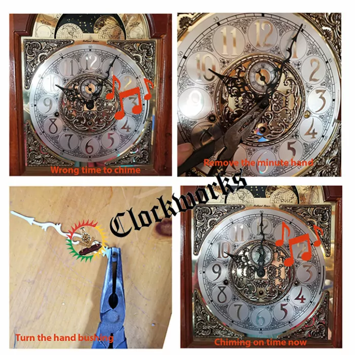
These are the directions to get a German mechanical clock to chime on time. This means having the clock hands point to the right spot when the clock chimes.
When replacing a clock movement, or getting new clock hands, either one, you will notice it will chime 5 minutes before it should, or 10 min after, something like this. This page explains how to correct this situation. It is unbelievably fast and easy to do.
Working with the minute hand
After the installation of a new mechanical movement , or if you are just installing a new set of hands, you may notice the clock will not chime at the time it should.
To correct this, take the minute hand off of the clock. This is the longer of the two hands.
With this minute hand off of the clock, turn it upside down and look that it has a square hole where it attaches to the clock. This square hole is in a bushing that will rotate WITHIN the minute hand itself.
The correction
So, all to be done is just use needle nose pliers to turn this bushing ever so slightly. Put the hand back on the clock and see if it’s pointing to the correct place where it should chime.
If it is, then it all set and it will point to the exact place it should be pointing to. If it is still not right, take the hand off and try again. Once you get the minute hand to point to the correct chime you then set it to the correct time.
The conclusion
It is really that easy, there is nothing to do with the clock itself, only the minute hand. In other words, to put it in a silly way, take the minute hand off of the clock and walk to the garage with it.
Take it far, far away from the clock. When in your garage take needle nose pliers and turn the bushing within the hand itself. Then walk back to the clock and put it on. See if it's now pointing to the right spot.
A spot to put the clock
Mechanical Grandfather Clock Positioning
Mechanical Grandfather Clock Positioning in the house should be in a place with not much vibration. If having people or pets coming and going in that area would have to take this in account. The clock needs a firm foundation and located in a room that does not have much vibration on the floor. Its not mandatory but it will help if there is not so much vibration disruption to the operation of the movement.
Avoid positioning the top against the wall
The mechanical grandfather clock cannot be up against the wall on the top side of the case. If anchored to the wall it will need to be done in a way the clock case can move slightly side to side. This is why most wall clocks with the rubber feet on the back of the case. This is because in a sense the entire clock case is swinging with the pendulum.
What happens if the case cant swing
If the clock case cant swing it may cease to function when the weights meet the bob area. The rhythmic vibrations is attempting to move the weights and cant and at the same time its trying to keep momentum. This will just end up stopping the clock when the weights get to the area of the pendulum bob. It will not damage clock clock in any way only the clock will not run the 8 days like it should. Fix this by moving the top of the clock case away from the wall. The case is swinging with the movement and pendulum in a strange way and keeps everything moving.
The best clock positioning
The clock should be firmly set on the bottom side of the clock case on the floor, the top should be free to rock a little. The clock will be top heavy when the weights are all up, so the firm base is a good idea.
Volume of the grandfather clock chime
As there is no chime volume control on a mechanical grandfather clock. The only way to alter the tone volume is with positioning of the clock case. The clock case on a soft surface like a rug will be quieter than one that is on hardwood. The material the clock sits on will determine the volume of the chime sound.